Announcement

Collapse
No announcement yet.

"Enhanced Generator" from JPKBook

Collapse
X
 
  • Filter
  • Time
  • Show
Clear All
new posts

  • #91
    Hi Skywatcher,

    Good to keep exploring new configurations and to note what effects what. As another said recently, the circuit maybe simple but the behaviour is complex and who knows, even ones states of consciousness will affect the output! lol I am still revising my circuit to feed the drive battery with the output from the triple wound coil and had done so last week but had a mishap in that a wiring connection linked to the mode switch produced a battery short that melted a few things. I've been fortunate with such events so far but will get there hopefully this week and will run some comparisons tests of 'Radiant' versus 'Generator' mode with the new 'back popping' feed.

    The SA developer has tried similar himself but his rectified feed was not fully isolated from the other 4 coils so it will be interesting to so how my version does.

    I am aware of his solid state developments but have not seen the video from Patrick Kelly. I will get to such things, such as the 'Ainslee heater', in due course as another project but I do like the tangibility of a spinning rotor, especially when it is going to serve as a demonstration device for interested parties. It's quite hard to look at a box that is discretely vibrating away inside and say 'well look it's just doing its thing'.

    Jules
    'Consciousness came First'

    Comment


    • #92
      Hi julesP, good to know you are making experiments with this also.

      I built a solid state version, with the 555 timer and a STP12NB30 mosfet.

      I used the astable circuit as alexkor used and I have the on time at 10% at the moment and using the common ground configuration.

      We shall see how well this works.

      Oh yes, I have no doubt that consciousness can affect these things and just about everything else as well. Reality is malleable, unlike what we were taught.
      peace love light

      Comment


      • #93
        Hi Skywatcher,

        I have now seen Patrick Kelly's video detailing the new solid state generator developed by his South African contact. I'm converted! Such an elegant method and capable of easy ramping up of the output power by increasing the pulse frequency hitting the battery. The several thousand pulses/sec that are easily generated here are miles beyond the 100 pulses/sec or so created by my rotor. However, as a learning tool the rotor is important and I still have plenty to find out about what works best. While I was planning on building an Ainslie heater, a resonance based circuit, after my current project, I will go down this route to build a PIG (Pulsed Induction Generator) instead, especially as it employs some circuits that I will have already built. For those interested, the pdf for this newer solid state version is in my dropbox file set for this forum at: https://www.dropbox.com/sh/0y15dybr5...n2q6QhHCa?dl=0 and called 'Solid State Generator.pdf'.

        Later today I will post the results of my revised 'back popping' circuit. After investigation I found that none of my components had burnt out after all and that for some strange reason there was no volts on the Hall sensor + feed. So I shouted at it (in the way that only electronic circuits can make you do) and so it decided to play ball and work! Clearly the device is sensitive to my state of mind which perhaps is not that surprising when one recognises that it is connecting in some way to the energy field that is the substratum of reality.

        Jules
        Last edited by JulesP; 10-02-2018, 12:12 AM.
        'Consciousness came First'

        Comment


        • #94
          Readings with 'Back popping' circuit

          Hi all,

          I now have some results for the 'back popping' circuit revision to see how well one can keep the drive battery charged up while it still powers the circuit.

          The circuit revision involved using the three coils in the 'litzed' set to provide power back to the drive battery. In this arrangement coil 3 is powered by the drive battery, as with the other 4 main coils, but the current is fed through a separate FET so that coil 3 remains independent from the HV pathway of the other main coils and which is fed to one or more charging batteries. Coil 3 then induces HV pulses in 'slave' coils 1&2 which are fed via the rectifying bridge to the drive battery. The aim was to see if this 'back popping' option was sufficient to offset the drive battery discharge and to overcome the issues of charging and discharging at the same time and to note other effects.

          My tests were of short duration at only 3.5 mins each on account of the fact that second FET for coil 3 became very hot at each run and I thought it was likely to burn out, even with a heat sink. I reason that this is because coil 3, being shorter than coils 4-7, only had a a resistance of 4.8ohms and the current was higher than it might be. However, with coils 4-7 in parallel proving a net resistance of only 3.8 ohms, then the current through the main FET is going to be even more so something else is causing FET to run excessively hot. Despite the short test runs I believe they still indicate the presence or not of charging.

          The readings are displayed in the attached chart together with the circuit arrangements (1&2) for the measurements. My thoughts about these are as follows:

          Somewhat strangely, if the HV pathway from the slave coils is not connected to the drive battery, but instead to my potential divider to measure the pulses on a scope, while the other HV line from the other main coils is connected to the charging battery, then the rotor spins down to a stop. At the moment I can see no obvious reason why that would happen.

          Generator mode produced the greatest charging effect on a single separate charging battery with Classic mode resulting in only a small increase in voltage. In both modes the drive battery experienced a drop but less so with in Generator mode.

          When using 2 or 3 charging batteries, the difference between Generator and Classic mode is much less but with the former still making a bigger impact.

          From these results I think the best charging effects are on a single battery in generator mode, or that resulting from a battery switching system, since even a dedicated 'back popping' circuit cannot offset the issue of effective charging at the same time as a battery is in discharge mode. While I appreciate that this was already well understood, I needed to quantify the issue before moving on to the next option of building a battery switching system.

          Any thoughts regarding why FET 2 got so hot and also why I was unable to measure the slave coils' HV pulses, while the rest of the circuit remained connected, would be appreciated.

          Regards,

          Jules
          Attached Files
          Last edited by JulesP; 10-02-2018, 01:54 AM.
          'Consciousness came First'

          Comment


          • #95
            Hi Jules,

            Originally posted by JulesP View Post
            Hi all,

            .................................................. .......................

            Any thoughts regarding why FET 2 got so hot and also why I was unable to measure the slave coils' HV pulses, while the rest of the circuit remained connected, would be appreciated.

            Regards,

            Jules
            Usually when a switching FET gets hot it's because it isn't conducting in saturated mode. This could indicate a problem in the trigger circuit for that particular FET and maybe even a damaged FET. Too long of a duty cycle could also add to over heating.

            Have no answer for the second question unless maybe the drive battery voltage is being pulled down to low by the total load applied.

            Comment


            • #96
              Hi Gary, Michael, Skywatcher et al.,

              I'm hoping to have the revised rotor based circuit (two batteries and a swapping circuit) ready in a couple of weeks with some COP estimates. Meanwhile I attach a schematic for the solid state version that has attracted a lot of attention via Patrick Kelly's recent video. This can be seen at: https://www.youtube.com/watch?v=EyN7...Emq59eP&t=979s and I have previously given a link for the relevant pdf doc.

              I'm already gathering parts for this 1-2kW PIG (Pulsed Induction Generator) for a build over the winter.

              Jules
              Attached Files
              Last edited by JulesP; 10-08-2018, 01:20 AM.
              'Consciousness came First'

              Comment


              • #97
                Hi all, Hi julesP, thanks for sharing, yes that circuit looks proper.
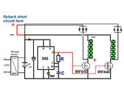
                The solid state version patrick kelly is showing, does not include a common ground, in fact, it shows the flyback being short circuited, I will assume it is a drawing error.
                Your circuit is a common ground version.
                I will be rewiring mine for the common ground setup, as I was testing the other ufopolitics type version and it works well, though I think for our purposes, we need the common ground for the efficiency and to replicate the south african version.

                peace love light

                Comment


                • #98
                  Hi Skywatcher,

                  My own schematic was not an exact copy opf what PK showed in the pdf and video but based on how I understood it worked. Can you pin point the 'flyback' on a pic so I can see what you are referring to?

                  Julian
                  'Consciousness came First'

                  Comment


                  • #99
                    Hi julesP, here is a pic from the pdf showing the short circuiting of the flyback.

                    peace love light

                    Comment


                    • Hi Skywatcher,

                      Well now you have pointed it out I don't think it's a mistake as many of the 'developer's' circuits have that configuration. It's a variation on the Classic or Radiant mode and where the connection back to the coil occurs before the positive terminal of the battery being charged instead of after the negative. Look at Arrangements 1&3 in the attached doc of some of my measurements compared to Arrangement 4.

                      Earlier in this thread Gary raised the same point and I conferred with the 'developer' and Patrick on the matter. Whereas for normal DC, this pathway constitutes a short and powers the coils when the Hall sensor triggers, to an HV pulse, with a width of say 20uS, the coil behaves as an open circuit as its has such a massive impedance to the short duration transient.

                      I have tried to show which understanding is right experimentally but once the HV pulse is connected to a battery it 'disappears' from a scope as its been absorbed so practically speaking it's unresolved. The developer argues that he has has his drive battery charging in Arrangement 1 which would suggest that the HV doesn't take a route through the coil and has no where to go except to the battery. I just haven't seen that myself.

                      Returning to the solid state version, I used the simplified circuit near the end of the pdf (attached) to come up with my schematic but I do have one query regarding this whole approach. Given that this design can produce much greater HV pulse rates of the order of > 2kHz, with consequently much greater vacuum energy input, how can one get that out to a load easily, via an inverter, from one or two modest 12V batteries? In conventional thinking to deliver even 1kW of power to the input side of the inverter at 12V would require over 83Amps from whichever battery is providing the supply at that moment. The solution may be that the HV pulses themselves provide most of the input power to the inverter as 'cold' electricity in which case the role of the battery is more to act as a 'smoothing sponge'.

                      I would appreciate any thoughts on how one can best output powers in the range 1-3kW.

                      Jules
                      Attached Files
                      Last edited by JulesP; 10-10-2018, 01:28 AM.
                      'Consciousness came First'

                      Comment


                      • Extracting >500W from a solid state generator

                        Hi all,

                        Recently I have been pondering and playing with various designs and configurations to allow upwards of 1000W to be drawn from a high frequency (>1kHz) HV pulse solid state device. The problem is that if a suitable inverter is being supplied from a 12V battery then the current demand to supply 1000W is going to be of the order of 83A. The use of a capacitor here is helpful, for not only does it translate the radiant energy to its 'positive' form but it benefits from the 'electret' effect. Even so, when the capacitor supplies current to the inverter it is going to have to deliver the very high amperage to provide the power.

                        My suggestion at this stage is shown in the 'Battery Config 3' pic. Here I have increased the number of batters to 4 offering 48V to the inverter and reducing the current drawn to 25% of that at 12V so 1kW will be approaching 21A. The voltage across the 10uf capacitor is anchored to 48V by the batteries and supplies the current to the inverter. If the voltage on the capacitor rises above 48V, for example when the inverter is not drawing any power, then it passes that energy to the battery stack via the three diodes. Note that the battery stack itself cannot deliver any power to the inverter through the reversed bias diodes. This is a test that the 'developer' has done to confirm that the LEDs that he used as the load, were being powered only by the HV and not using any battery power.

                        The circuit itself then draws its power from either a Buck Converter fed from the 48V stack, or by a direct feed from the bottom 12V battery in the stack. Which option is best would depend on how the back feed through the diodes was distributed amongst the batteries.

                        Any thoughts about this suggestion would be appreciated.

                        Jules
                        Attached Files
                        'Consciousness came First'

                        Comment


                        • Rotor generator and revised battery swapper

                          Hi all,

                          I wanted to update on the modifications I have made to the rotor based system with the addition of an effective battery swapper. When I built and installed the first one, it was found that both batteries had some current drain all the time and that was to feed either the transistor bases or the timer and relay circuit, even though the main coil current was alternated. So I revised the design so that each battery is fully in either charge or discharge mode. This included the use of a 39,000uf capacitor to supply the timer and relay circuit during the relay's brief switch over. The swap time is set to 30 seconds and this revised circuit is attached as 'Battery Swapper (Revised)'. I also have a 3 min video of the whole generator running at: https://www.dropbox.com/sh/kjcs6exru...YqrlyIyWa?dl=0

                          As I say in the video, the rotor speed may be pivotal in delivering the required rate of pulses to keep the system self sustaining and to power an additional external load although I doubt these things behave in a logical manner. The break point for self running I believe to be about 1,400 rpm in my case, that's about 117Hz HV pulses. Freshly lubricating the bearing can help there but in an ideal world I would substitute the ball bearing from the type used in computer hard drives that have much less friction.

                          I also attach the schematic for a solid state version I am building that uses 7 coils, each being fed from a timer and cascade circuit with preset timer periods resulting in HV pulse frequencies ranging from 500 - 3,500Hz but easily changeable to much higher values. Given the need to operate with 12V lead acid batteries, and the potential for high output currents for the inverter, I am running with 36V and using an electromechanical relay for the battery swapper. A buck converter is then required to provide suitable voltages to the main circuit.

                          I will update here when I have something more substantial to show.

                          Jules
                          Attached Files
                          'Consciousness came First'

                          Comment


                          • Hi Gregory,

                            I went to look at the 10kW household generator at your site but there's just the title and no details? What type of generator is it and what principles is it using?

                            Jules
                            'Consciousness came First'

                            Comment


                            • Hi julesP, I have also just yesterday continued testing with this type of setup, was working on a heater previously.

                              I am using only one bifilar coil/core as drive and the other 3 coil/cores as separate generator coils in series.

                              Using that generator output to light a 12 volt led bulb off a full wave bridge with large 1.5 farad car audio capacitor to smooth output to the bulb, other wise it flickers a little.

                              I'm doing this to place a mechanical load on the device, to then see if the batteries can still maintain voltage and charge over time.

                              It is using .42 amps in this configuration, using the same 12 volt tractor batteries, running for an hour, letting rest for awhile, then swapping.

                              peace love light
                              Last edited by SkyWatcher; 11-11-2018, 11:02 AM.

                              Comment


                              • Solid State Generator Update and some Battery queries (Part 1)

                                Hi all,

                                I wanted to give an update on my build of the Solid State Version of the generator that was released via Patrick Kelly a couple of months ago. For those who are new to this particular configuration, I refer to it as a PIG (Pulsed Induction Generator) and instead of using a rotor with magnets and a Hall sensor to trigger a set of coils to turn on and then off again, hence producing the HV spikes to charge a battery, a 555 timer chip is used in conjunction with a CD4017 decade counter IC to sequentially fire a series of coils; as many as you care to construct.

                                The reason why the coils are fired sequentially rather than all together, and which a single FET could manage very well, is for two reasons. Firstly the smaller windings of each coil, 7 of them in my case, result in a resistance of less than 2 Ohms each. Seven of these in parallel would result in just over 0.25 Ohms with consequently a very high instantaneous current value. Secondly, should one wish to operate the square wave generator at say at 50kHz, each coil is in fact only firing at 1/7th of that frequency which, even with the ferrite cores being used, will be easier for them to manage. As each coil is carefully hand wound and five layers deep on 140mm ferrite cores, I felt that 7 was enough!

                                My rotor based system, which I am still working on to glean the most information and experience, typically outputs HV pulses of 1,200V p2p at a frequency of 100-125Hz depending on the rotor rpm which in turn is influenced by the friction in the roller bearing which in turn is influenced the ambient temperature (in my workshop it can get quite cold at times). In contrast the solid state version produces HV pulses of around 500V p2p but at a range of frequencies from 500-5,000Hz (and easily adjustable up to 100kHz and beyond if the coils can respond well) and selected via a set of preset resistance trimmers on the timer board for fine tuning. I am also using a cheaply obtained PWM module that can produce pulses from 1Hz-150kHz and with variable Duty cycle and nicely displayed on a readout. As you can imagine this is depositing a significantly larger amount of energy into the battery.

                                Images of the schematic, the build so far, coil construction, the square wave module and output waveforms at various frequencies are at the following link: https://www.dropbox.com/sh/82ys1n2p4...drKTtvBQa?dl=0

                                It is interesting to note how the HV pulse waveform changes as the frequency is increased. At 100Hz, my typical rotor based frequency, they are very distinct where as at 2kHz they are merging a bit so that the minimum voltage is increased. At 4kHz they become very distinct again and at 5kHz more blended. I am working on the theory that it is the rising edge that indicates how well the 'vacuum gets smacked' and the space-time warped and also that there are likely to be resonant points in the frequency range where optimum energy flow and battery charging occurs. This aspects will make for some interesting measurements and when the build is complete I plan to use a resistive heating element with an SCR Voltage regulator to provide a variable load for the inverter to see how the generator performs.

                                So my build is 80% complete in that I can now produce high frequency pulses and observe the effects on a single 7Ah battery while a separate battery provides for the circuit. The schematic shows that I am feeding the inverter with 36V so that the current demand at a nominal 1kW will be manageable by the small SLA batteries. To that end I am using two banks of 3 batteries and have yet to build the battery swapper that will use an automotive electromechanical relay capable of switching 30-40A. Also I need to sort out the best way to channel the HV pulses to the battery banks and regulate the energy input. Hence the request for guidance that follows.

                                Continued in the next post . . . .

                                Jules
                                Last edited by JulesP; 11-28-2018, 02:37 AM.
                                'Consciousness came First'

                                Comment

                                Working...
                                X