If this is your first visit, be sure to
check out the FAQ by clicking the
link above. You may have to register
before you can post: click the register link above to proceed. To start viewing messages,
select the forum that you want to visit from the selection below.
sorry to be clear, I am talking about that waveform appearing in the 3GT. following the trhread on energetic that waveform is based on polarity switching by the rotor.2 short pulses and take out the power as john says. with an all north rotor it will be interesting to see how switching the coils with the full B/C circuit will affect the wave coming out of the coil.
never saw the waveform before the FWBR only going into the cap and out to the battery.
Tom C
Are you talking about the bottom 3 coils on the 3GT part, or the hub w/ the memory magnets? Trying to keep things straight in my head.
The MW wave form in jerdee's post is very easy to achieve w/ two coils in series. the coils separated should create their own sine wave, one should be inverted from the other. ALSO, one coil should have less resistance than the other, then simply move the coils until the waves overlap... poof! you have the cool MW wave. now, play around with their locations and resistances a bit more...
These waves can also be produced w/ a single stranded coil, but then you might have a psychotic coil that talks to itself and not much else - LOL
now the next step is to get that pulse out of the waveform and into another coil that will affect that coil. how would you bias that wave with another coil like the slave coils and turn it square? the pulse is flipping the pmh like a radus boot. like bearden said clever switching keep the chatter up gentlemen, the nut is almost cracked!!
now the next step is to get that pulse out of the waveform and into another coil that will affect that coil. how would you bias that wave with another coil like the slave coils and turn it square? the pulse is flipping the pmh like a radus boot. like bearden said clever switching keep the chatter up gentlemen, the nut is almost cracked!!
Jerdee,
Thanks for posting that schematic, i was looking for that exact setup, thank you. I was not at the conference so im having a hard time following what you saw on how john was switching. But i think i have a good idea on how its done. Below is a picture of what ive been doing. The point the switching should start (i believe) is just before the magnet reaches midpoint. Using a repulsive pulse going right up to midpoint or slightly after. Right at that point the next upcoming magnet should switch into the cores domain (if that makes sense) just like the radus demo. At that point the pulse ends and the magnets take over and suck themselves into the core, rotating the wheel. Then it starts all over again on the next midpoint but in the opposite polarity. Pulse width should be set as small as possible, just enough to switch the field(radus effect). By switching this way, your wheel will rotate slowly, because your not providing energy to turn the wheel, the magnets are doing the work and they work at thier own pace. This is how i see it currently but i will have a much better idea of just how well it works when i get the parts for the Bedini/Cole switch in the schematic you posted.
In between pulses, we should be able to extract a certain percent of energy from the magnets passing the cores as well either directly with the bridge rectifier or with a shorting magneto effect.
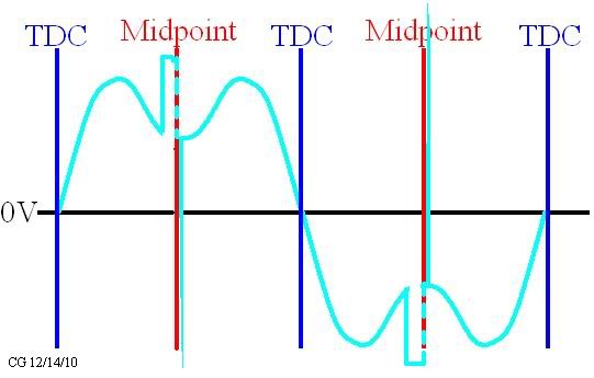
This is what the scope shot across the coils looks like with pulse locations. My setup does not generate a perfect sign wave, so i have drawn it as it is. You can see im pulsing on both polarities.
It is, you are correct. I've used it on the window motor B kit to chop up the input. since that kit's geometry is off, it really helped to get more energy out of it, so my mind wondered when I posted that. Back on track now...
Patrick A.
"Electricity,
The mystery is none as it is right in front of you. I will give it to you again.
The machine requires one DC motor, 555 timer circuit for pulses to chop the DC motor, one mono pole energizer and one large mass weight wheel. the two signals are out of phase from each other. and a capacitor tuned to the energizer. That is the mystery. other then that some simple wiring, you wont do it on a small scale. As I said it is right in front of your eyes. It's the way you think about it.
On a big scale it's very easy to work on. simple logic the bigger the generator section is the slower you must turn it. since it is not a conventional generator you must store the charge before you discharge
the capacitors to the batteries. If the timing is right the batteries charge right up to full.
It's your own mind stopping you from success as your own mind understands what your intentions are, that is what is stopping you.
All your questions have been answered for years. Very easy to see that once the machine works we will never here of you again."
That is a very interesting quote. It is strange how you can apply that same principle to different devices. The Kromrey Converter, for instance, runs in a very similar way.
I believe that the ferris wheel allows for more magnets, which therefore increases the frequency of the discharge of the coils.
The frequency must reach a resonance based on the capacitance of the circuit. I would guess that you would want a small capacitance for higher frequencies of discharge to see higher efficiency. Try increasing the frequency and decreasing the capacitance and see how that effects performance.
-Ajay
"Electricity,
The mystery is none as it is right in front of you. I will give it to you again.
The machine requires one DC motor, 555 timer circuit for pulses to chop the DC motor, one mono pole energizer and one large mass weight wheel. the two signals are out of phase from each other. and a capacitor tuned to the energizer. That is the mystery. other then that some simple wiring, you wont do it on a small scale. As I said it is right in front of your eyes. It's the way you think about it.
On a big scale it's very easy to work on. simple logic the bigger the generator section is the slower you must turn it. since it is not a conventional generator you must store the charge before you discharge
the capacitors to the batteries. If the timing is right the batteries charge right up to full.
It's your own mind stopping you from success as your own mind understands what your intentions are, that is what is stopping you.
All your questions have been answered for years. Very easy to see that once the machine works we will never here of you again."
the timing needs to have adjustable dwell and location, the round magnets do a great job of adjusting both. looka like you already have a disc, but looks like they are neo..... how hard would it be to replace with ceramics? that coil should work, the slave coils they need to be half the height, same diameter, should work out to half the inductance. steel for the coil shield. bonded to the rods either by some copper strips or touching some other way.
Hey Tom - 1GT so far...
had some quiet time to layout a plan and get it spinning. I've decided to use this smaller wheel w/ 16 magnets rather than the 6' wheel I made. I don't have enough wire for that big boy. 3 things:
1. I'm thinking of using the magnets on the outer rim for timing the hall. I think John used 50/50 timing w/ that highly modified Bedini/Cole switch on an inner timing wheel. Do you think we should plan the same thing for these smaller wheels?
I'm hoping to use the plexi wheel in the pic below for my light lenz generator, but I'm sure I can fix some smaller magnets toward the center.
2. Coil - the one I've selected has two windings, one that is 1/2 of the other that paralleled = 2.6ohms - thoughts?
3. coil shaping metal for the base center coil... I can't remember what kind of metal - Iron? and was it welded to the rods or just filed down rods so they made full contact?
I'll solder up the ckt and get some thick leads on there the next chance I get. Not even time to make a vid - Thanks for any help.
Kind Regards,
Patrick A.
 keep the chatter up gentlemen, the nut is almost cracked!!
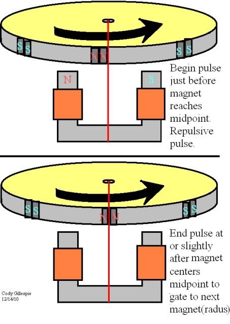

Leave a comment: